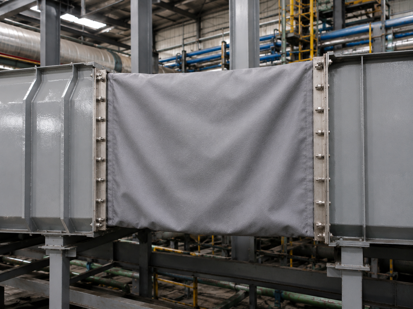
Large rectangular and circular flue gas duct systems, especially in the DN1500–DN4000 range, face unique thermal expansion and mechanical movement challenges.
As duct temperatures change during startup, shutdown, load variation, and normal operation, large duct structures can experience significant axial, lateral, and angular movement.
While metallic bellows are highly effective in many pressure piping applications, large low-pressure flue gas ducts often require a different approach.
For these applications, the key challenge is not simply absorbing movement.
It is absorbing large multidirectional movement without imposing excessive reaction forces on the duct structure while maintaining resistance to heat, moisture, and corrosive flue gas.
Large flue gas ducts are fundamentally different from conventional pressure pipelines.
Their wall thickness and supporting structures are often optimized for low-pressure gas flow rather than high mechanical reaction loads.
When an expansion joint generates significant spring forces during movement, these forces can be transferred into duct supports, equipment nozzles, and surrounding structures.
At the same time, flue gas chemistry can create a highly aggressive environment during temperature transitions.
Two major challenges therefore need to be considered.
Metallic bellows rely on the elastic deformation of corrugated metal elements to absorb movement.
As the bellows deform, they generate reaction forces.
For a large flue gas duct, these forces can become an important design consideration, particularly when the system requires substantial lateral or multidirectional movement.
For example, accommodating approximately 100 mm of lateral movement may require specialized bellows geometry, multiple plies, additional structural components, or more complex guiding and support arrangements.
Increased load on duct supports
Additional structural reinforcement requirements
Higher loads at equipment connections
More complicated support and guiding systems
Increased installation complexity
For large low-pressure ducts, movement capacity is only one part of the engineering equation. Reaction force is equally important.
Flue gas systems can contain sulfur compounds, moisture, and other corrosive constituents depending on the fuel and process.
During startup, shutdown, or abnormal operating conditions, flue gas temperature may fall below the acid or water dew point.
When this occurs, corrosive condensate can form on internal metal surfaces.
Stainless steel grades such as 304 and 316L provide good corrosion resistance in many industrial environments, but material selection must always consider the actual gas composition, temperature, condensate chemistry, and operating cycle.
Localized corrosion
Pitting
Crevice corrosion
Condensate accumulation
Reduced bellows service life
This is particularly important in biomass combustion, waste-to-energy, FGD, and other flue gas applications where gas chemistry can vary significantly.
For large flue gas ducts where low reaction force, multidirectional flexibility, thermal insulation, and chemical resistance are critical, B-NAI non-metallic fabric expansion joints provide an alternative to conventional metallic bellows.
The expansion joint is engineered as a multi-layer composite system, with each layer performing a specific function.
Instead of relying on a single metallic bellows element, the construction combines flexible fabrics, protective coatings, sealing membranes, insulation layers, and reinforcement materials according to the operating conditions.
*Actual allowable temperature depends on the complete material construction, gas composition, insulation arrangement, movement requirements, and operating conditions.
The outer layer provides mechanical protection and environmental resistance.
Depending on the application, heavy-duty silicone-coated fiberglass or fluoroelastomer-coated fabric can be selected to resist:
External weather exposure
Moisture
Chemical vapors
UV exposure
Industrial environmental conditions
The outer coating also helps protect the internal composite layers from external contamination.
A PTFE membrane can be incorporated as an internal sealing and chemical-resistant layer.
Its primary function is to limit the penetration of corrosive gases and condensate into the insulation and structural fabric layers.
Chemical resistance
Gas sealing
Condensate resistance
Protection of internal insulation
Separation of aggressive media from sensitive layers
The insulation package is designed to reduce heat transfer from the hot flue gas toward the outer flexible layers.
Depending on the temperature and construction requirements, the insulation system may incorporate:
Ceramic fiber blankets
High-silica woven materials
Fiberglass materials
Other application-specific thermal barriers
The insulation system helps maintain the temperature of the external flexible layers within their allowable operating range.
The internal fabric structure is designed to maintain mechanical integrity while allowing the expansion joint to flex.
The exact layer sequence, fabric type, reinforcement, thickness, and attachment method can be customized according to:
Duct size
Operating temperature
Gas composition
Pressure
Movement
Installation configuration
Required service life
One of the most important advantages of a properly designed non-metallic fabric expansion joint is its low spring force compared with many metallic bellows configurations.
The flexible fabric assembly can accommodate large axial, lateral, and angular movements without relying on a rigid corrugated metal element.
This can help reduce the mechanical loads transferred to lightweight ductwork and supporting structures.
Axial movement
Lateral movement
Angular movement
Multidirectional movement
Thermal expansion
Equipment vibration
The objective is not simply to absorb movement. It is to absorb movement while minimizing unnecessary structural loading.
A large expansion joint cannot simply be scaled up from a small-diameter design.
As duct dimensions increase, the design must consider the complete system:
Rectangular and circular ducts create different movement and sealing requirements.
Axial, lateral, and angular movements may occur simultaneously.
Continuous operating temperature and transient temperature conditions must both be considered.
Sulfur compounds, moisture, chlorides, dust, and other contaminants can influence material selection.
Even low-pressure duct systems require proper consideration of positive and negative pressure conditions.
The insulation package must protect flexible materials from excessive thermal exposure.
Frame design, flange configuration, liner arrangement, and installation clearances directly affect expansion joint performance.
B-NAI fabric expansion joints are manufactured according to the actual requirements of each duct system.
Typical applications include:
Flue Gas Desulfurization systems can expose expansion joints to moisture, chemical compounds, temperature fluctuations, and corrosive condensate.
Large boiler and exhaust ducts require reliable accommodation of thermal and mechanical movement.
Variable fuel composition can produce complex flue gas chemistry and changing operating conditions.
High-temperature exhaust gases and corrosive compounds require carefully selected flexible materials.
Large thermal movements and high-temperature dust-laden gases create demanding operating conditions.
High-temperature exhaust systems require flexible connections capable of accommodating thermal movement while protecting surrounding structures.
| Engineering Requirement | Metallic Bellows | Non-Metallic Fabric Expansion Joint |
|---|---|---|
| High-temperature pressure piping | Excellent | Application-dependent |
| Large duct movement | Application-dependent | Excellent |
| Low reaction force | Limited by bellows stiffness | Major advantage |
| Multidirectional movement | Possible | Excellent |
| Thermal insulation | Limited | Integrated into composite design |
| Corrosive flue gas | Material-dependent | Multi-layer chemical barrier available |
| Large rectangular ducts | More complex | Well suited |
| Low-pressure duct systems | Application-dependent | Particularly suitable |
| Custom layer construction | Limited | Highly configurable |
The right expansion joint depends on the system — not simply on the temperature or diameter.
B-NAI does not treat fabric expansion joints as one-size-fits-all components.
Each project can be evaluated according to:
Duct Size · Temperature · Pressure · Gas Composition · Movement · Insulation · Connection Design · Installation Conditions
Based on these parameters, the fabric expansion joint can be configured with the appropriate combination of coating, membrane, insulation, reinforcement, and structural layers.
A fabric expansion joint is only as reliable as the materials selected for its actual service conditions.
B-NAI focuses on matching each layer to its specific function.
Protection against weather, UV, moisture, and external chemical exposure.
Protection against corrosive gases and condensate penetration.
Thermal protection for temperature-sensitive flexible materials.
Mechanical strength and dimensional stability.
Controlled movement and low reaction force.
One expansion joint. Multiple engineered layers. One integrated system.
For large rectangular and circular flue gas ducts, the challenge is not simply finding an expansion joint that can move.
The real challenge is finding a design that can accommodate movement while controlling reaction forces, resisting the actual chemical environment, and protecting the flexible materials from excessive temperature.
B-NAI multi-layer fabric expansion joints are engineered around these requirements.
From FGD systems and biomass plants to cement kilns, waste-to-energy facilities, and industrial furnaces, our fabric expansion joints provide a flexible solution for demanding duct applications.
Large Movement. Low Reaction Force. Multi-Layer Protection.
Provide us with your basic operating conditions, and our engineering team can help determine the appropriate fabric expansion joint construction.
Duct Size
Rectangular or Circular Configuration
Operating Temperature
Maximum Temperature
Working Pressure
Positive / Negative Pressure
Flue Gas Composition
Axial Movement
Lateral Movement
Angular Movement
Connection / Flange Dimensions
Insulation Requirements
Quantity
Project Application
Engineered for Movement. Built for Extreme Conditions.